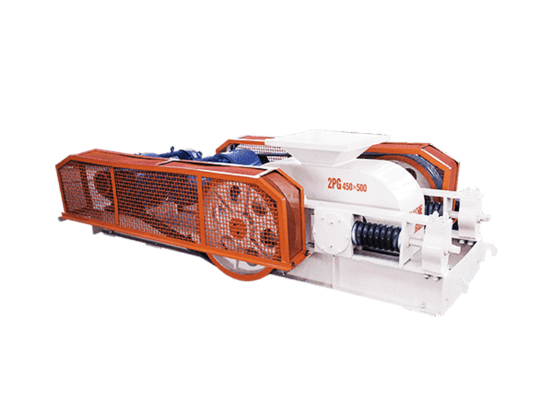
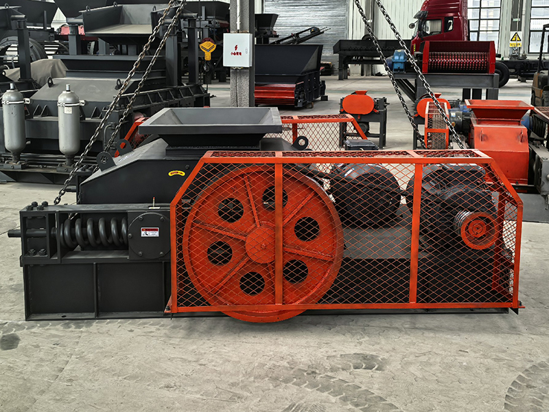
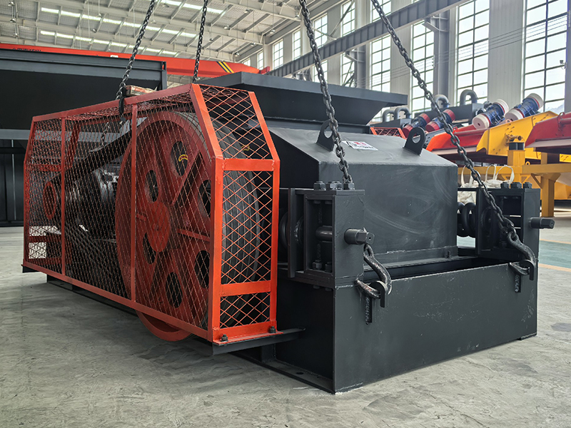
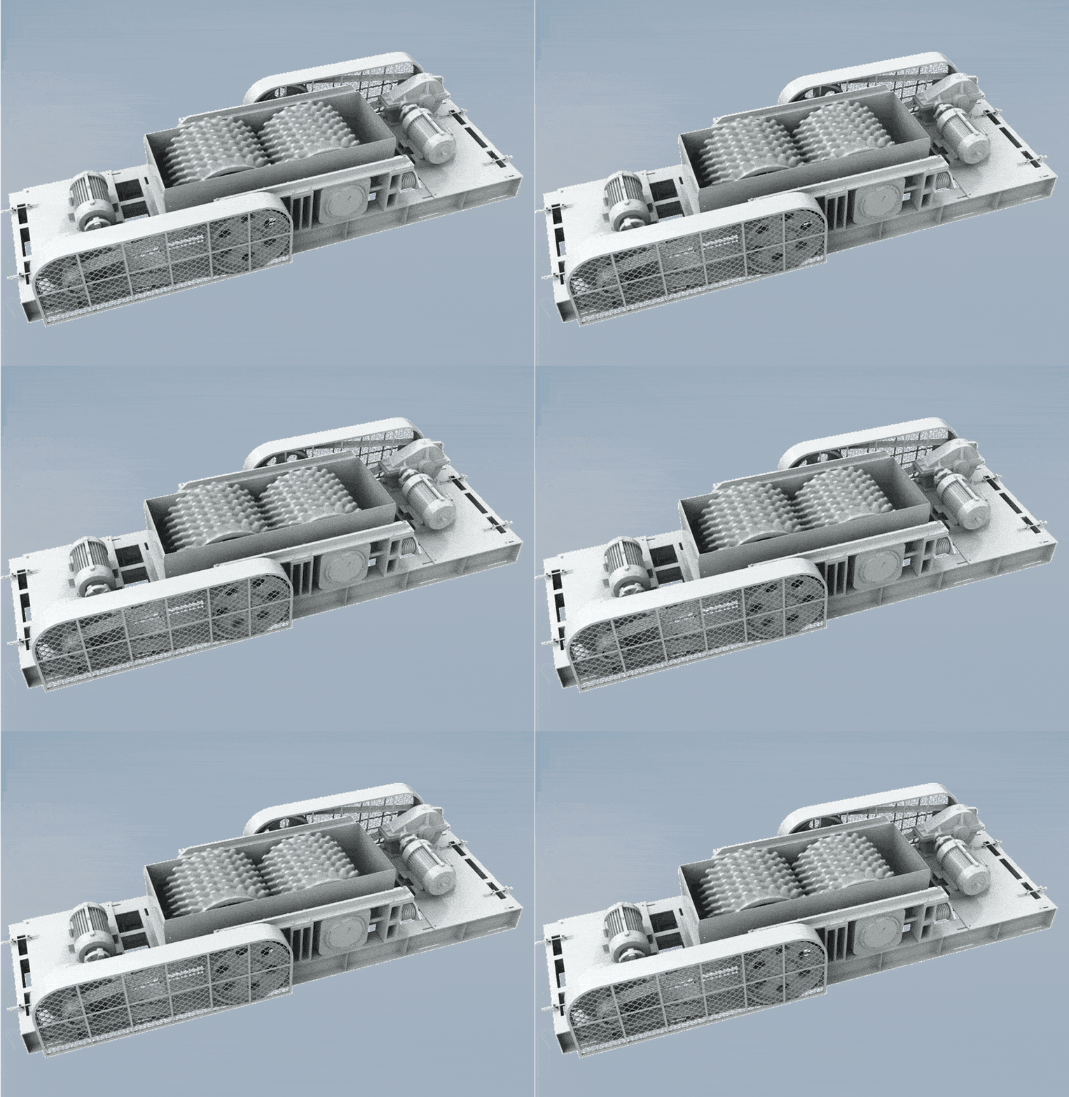
The double roll crusher, also known as a twin-roll crusher, is a high-efficiency crushing equipment composed of two counter-rotating crushing rollers. Material enters from the top between the two rollers and is crushed by compression, shearing, and splitting forces. This equipment uses high-quality alloy wear-resistant roller shells, ensuring a long service life. The crushing ratio is adjustable, and the output particle size is uniform. It is widely used in the coarse and fine crushing of various medium-hardness materials.
Core Components of the Equipment
1. Frame: Made of high-strength steel, supporting the entire equipment structure.
2. Crushing Rollers: The core working components, including a fixed roller and a movable roller, with wear-resistant roller shells on the surface.
3. Transmission Device: Includes motor, reducer, coupling, gears, etc., providing crushing power.
4. Adjustment Device: Hydraulic or spring system, used to adjust the gap between the two rollers and control the output particle size.
Advantages and Features
Simple structure, easy maintenance: The entire machine has a compact structure, occupies a small area, and requires simple daily maintenance and low maintenance costs.
Adjustable particle size, uniform output: By adjusting the gap between the two rollers, the output particle size can be controlled to meet different production needs.
Overload protection, safe and reliable: Equipped with a hydraulic or spring adjustment device, it can automatically retract when encountering uncrushable objects, protecting the equipment.
Wear-resistant and durable, stable operation: The roller surface is made of high wear-resistant alloy material, ensuring a long service life and stable and reliable equipment operation.
Working Principle
The working principle of a double-roll crusher is based on the crushing of
materials by two counter-rotating crushing rollers:
The material falls into the gap between the two rollers from the feed opening.
Under the action of friction and gravity, the material is drawn into the crushing chamber.
The two rollers rotate in opposite directions, generating strong compressive and shearing forces on the material.
The material is crushed under pressure, and after reaching the desired particle size, it is discharged from below.
The gap between the two rollers determines the size of the output particles, and this gap can be adjusted by an adjustment device.
Technical Parameters
Model
Roller diameter (mm)
Feeding size (mm)
Discharge size (mm)
Output (t/h)
Power (kw)
2PG400×250
φ400
<25
≤3
5‑10
5.5×2
2PG450×500
φ450
<30
≤3
8‑20
7.5×2
2PG610×400
φ610
<30
≤3
13‑35
15×2
2PG610×750
φ610
<30
≤3
16‑40
22×2
2PG750×500
φ750
<30
≤3
16‑40
22×2
2PG800×600
φ800
<30
≤3
20‑40
30×2
2PG800×800
φ800
<30
≤5
20‑50
37×2
2PGY1000×800
φ1000
<30
≤5
40‑70
55×2
2PGY1200×1000
φ1200
<30
≤5
60‑100
90×2
2PGY1200×1200
φ1200
<30
≤5
80‑130
110×2
2PGY1500×1000
φ1500
<30
≤5
100‑150
132×2
2PGY1500×1200
φ1500
<30
≤5
150‑200
160×2
2PGY1800×1000
φ1800
<30
≤5
220‑300
200×2
2PGY2000×1200
φ2000
<30
≤5
300‑400
250×2
Any change of technical data will not be advised separately.